September 2014 - December 2014. Read part 1.
Tessellation Factors
Tessellating a quad in DirectX11 is not quite as straight-forward as you might think. The simplest way to do it is to tessellate uniformly, turning 1 quad into 4 (or more). Uniform tessellation is relatively easy and is something I talk about more in my previous post.
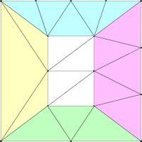
A much more interesting question is what if you apply different tessellation factors to different edges? DirectX11 lets you do this. For a quad there are actually 6 different tessellation factors: one for each edge and two for the centre. The image on the right (taken from Fabien "ryg" Giesen's Trip Through the Graphics Pipeline) shows an example tessellation. The yellow edge factor is 1, green is 2, pink is 3 and cyan is 4. The edge factors determine how many segments to split the original edge into. The horizontal inside factor is 3 and the vertical inside factor is 4; these determine how the inner (white) area is divided. In this case the total quad is split into 3 vertical sections (the leftmost and rightmost being handled by the yellow and pink edge factors) and 4 vertical sections (the top and bottom being the cyan and green edges).
A much more interesting question is what if you apply different tessellation factors to different edges? DirectX11 lets you do this. For a quad there are actually 6 different tessellation factors: one for each edge and two for the centre. The image on the right (taken from Fabien "ryg" Giesen's Trip Through the Graphics Pipeline) shows an example tessellation. The yellow edge factor is 1, green is 2, pink is 3 and cyan is 4. The edge factors determine how many segments to split the original edge into. The horizontal inside factor is 3 and the vertical inside factor is 4; these determine how the inner (white) area is divided. In this case the total quad is split into 3 vertical sections (the leftmost and rightmost being handled by the yellow and pink edge factors) and 4 vertical sections (the top and bottom being the cyan and green edges).
Proximity-based Tessellation
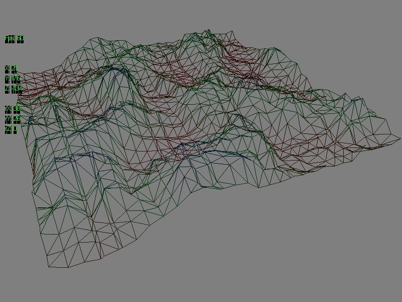
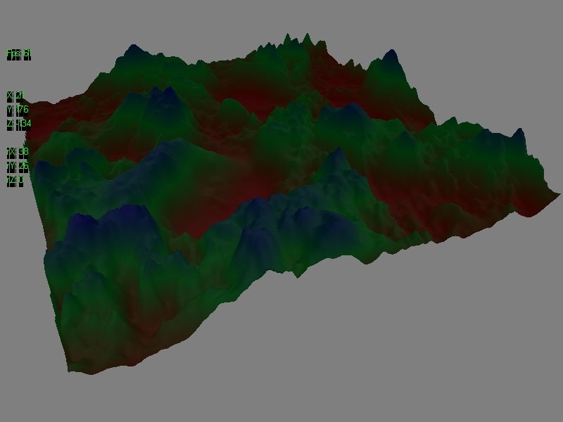
We could calculate a different tessellation factor for each quad but that would be blocky and likely introduce holes in the mesh. Instead we can go one further and calculate a different tessellation factor for each edge and the centre of each patch, giving as smooth a transition as possible. This is what I did with my terrain.
The tessellation factors for the initial 16 quad patches are calculated in the hull shader. The centre point of each edge is found and the tessellation factor for that edge is calculated by linearly interpolating (lerping) from the maximal factor (64) to the minimal (1) based on the ratio of the centre point distance against some control distance. For example if the distances we're talking about are from the origin (0, 0, 0), the current patch edge's centre point is at (50, 0, 0) and the control distance is 100; the ratio for that edge is 50/100 = 0.5, so the tessellation factor for that edge is 1 + 0.5(64 - 1) = 32.5 ~ 32. So if the centre of an edge is half the control distance away, it has half the maximum tessellation factor. Anything further than the control distance away has a tessellation factor of 1, i.e. no tessellation (just the original edge).
The inside tessellation factors are calculated as the average of the four edges; I tried a number of different schemes and found this to give the smoothest transitions between tessellation factors, both within a patch and between adjacent patches.
One big problem with non-uniform tessellation is that if two adjacent patches are tessellated with different factors it can introduce holes in the mesh since there are no longer the same number of shared edges along the boundary. One of the benefits of calculating factors on a per-edge basis is that common edges will have the same factor calculated each time, meaning adjacent patches always have the same number of shared edges and the mesh remains contiguous.
Geometry Shaders
The programmable parts of the graphics pipeline are, in order: vertex shader, hull shader, domain shader, geometry shader, pixel shader. Since I'm using the hull and domain shaders to tessellate the terrain, my domain shader effectively replaces the vertex shader since we don't have all our vertices until then. I've already discussed my pixel shaders for lighting the terrain and for performing post-processing in my previous post. The missing part (and one of the most interesting parts) is the geometry shader.
The geometry shader operates on entire primitives (points, lines or triangles, with or without adjacency information) and outputs a stream of such primitives. The interesting thing is that the output stream can be of a different type to the input primitive. For example the input primitive could be a single point and the output stream could be 2 triangles centred on the point to create a quad. This point-sprite expansion algorithm is an effective way of doing particle effects, for instance.
The geometry shader operates on entire primitives (points, lines or triangles, with or without adjacency information) and outputs a stream of such primitives. The interesting thing is that the output stream can be of a different type to the input primitive. For example the input primitive could be a single point and the output stream could be 2 triangles centred on the point to create a quad. This point-sprite expansion algorithm is an effective way of doing particle effects, for instance.
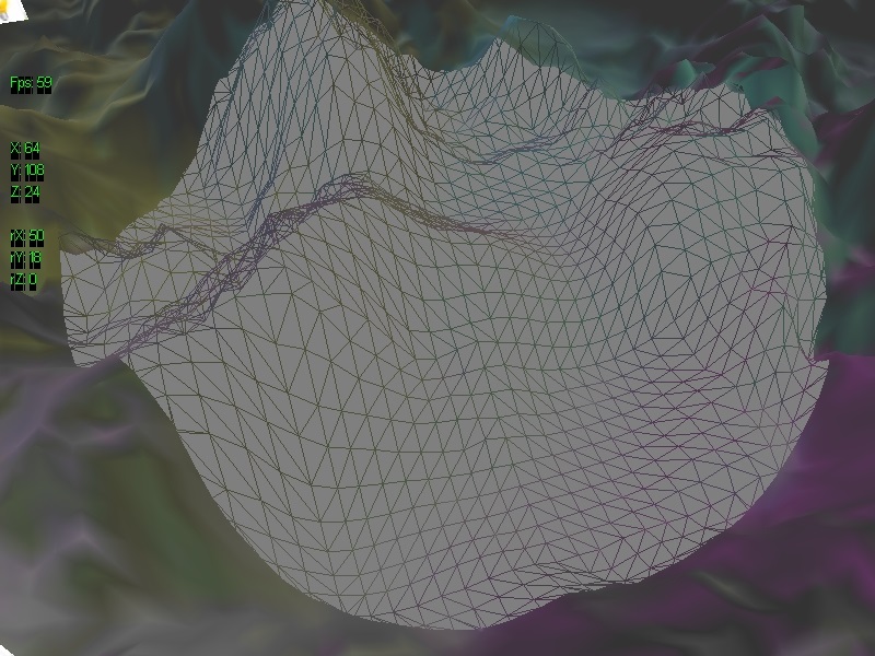
Proximity-based Wireframe
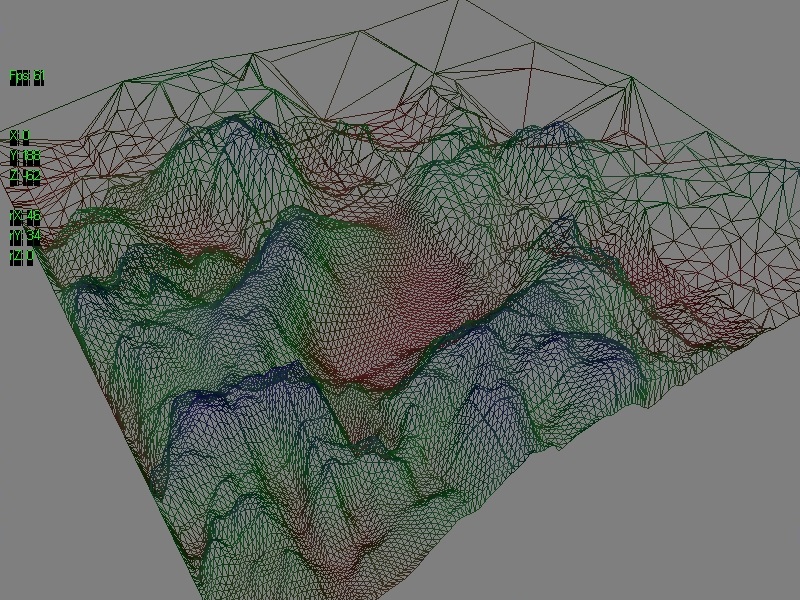
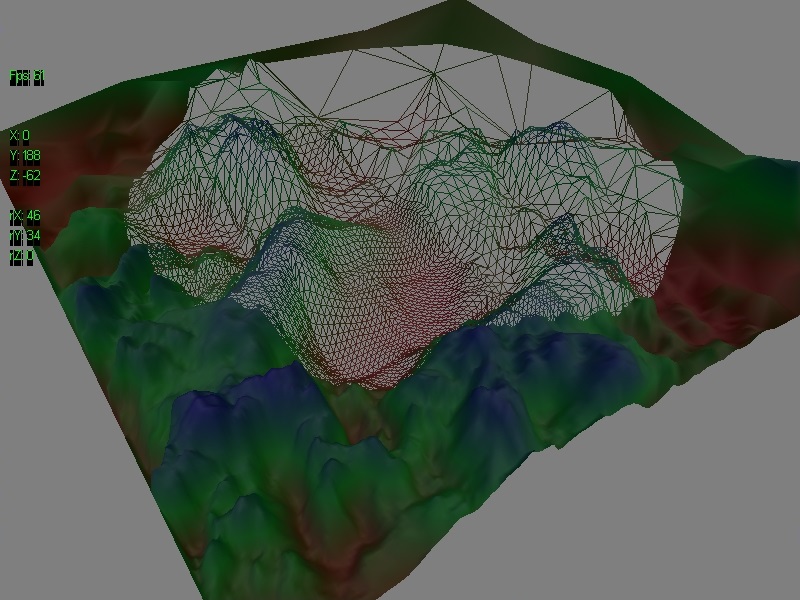
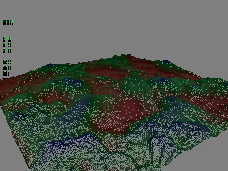
What I decided to do with geometry shaders was to create a proximity-based wireframe mode, so that triangles in a certain area are dynamically replaced with lines representing their edges instead of rendering the face itself:
In order to achieve this I created two different geometry shaders: one that outputs a triangle stream and one that outputs a line stream (this isn't possible to do with a single shader). The terrain is rendered with each geometry shader in turn, meaning it's rendered twice per frame, which isn't ideal but certainly for this application it was sufficient.
The two geometry shaders perform similar but mirrored operations. Again both shaders operate on a per-primitive (in this case per-triangle) basis. The first step is to work out whether each vertex is inside or outside the wireframe zone. There are 4 possible cases: all 3 vertices are inside the zone, all 3 vertices are outside the zone, 1 vertex is inside and 2 are outside, 2 vertices are inside and 1 is outside.
All 3 vertices inside the wireframe zone:
In this case the geometry shader outputting triangles will output nothing, effectively ignoring that triangle. The shader outputting lines will output 3 lines connecting the vertices together, creating a wireframe representation of that specific triangle.
All 3 vertices outside the wireframe zone:
Similarly in this case the shader outputting triangles will output a triangle representing the original input while the shader outputting lines will output nothing, ignoring it.
The interesting cases are when only one or two vertices are inside the wireframe zone. In these cases the original triangle is split into 3 sub-triangles.
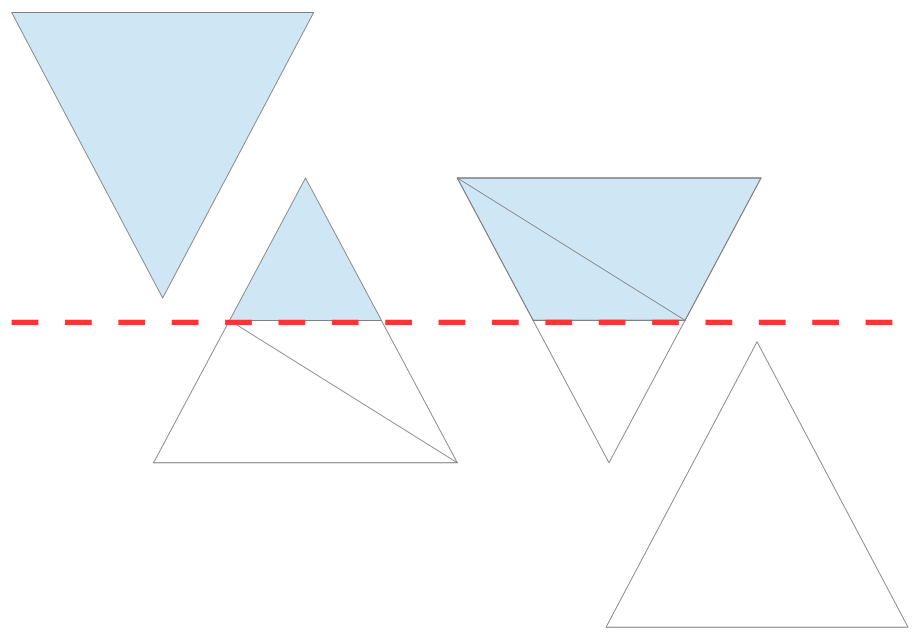
2 vertices inside wireframe zone, 1 outside:
Since we know which specific vertex is outside the wireframe zone we know which edges of the triangle intersect the zone boundary. By finding the intersection points we can have the triangle-outputting shader output a filled sub-triangle up to the zone boundary and the line-outputting shader output wireframe representations of the remaining two sub-triangles, or vice-versa for 1 vertex inside wireframe zone, 2 outside.
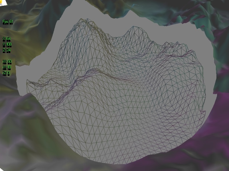
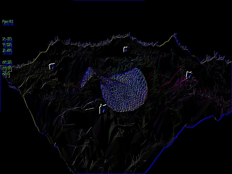
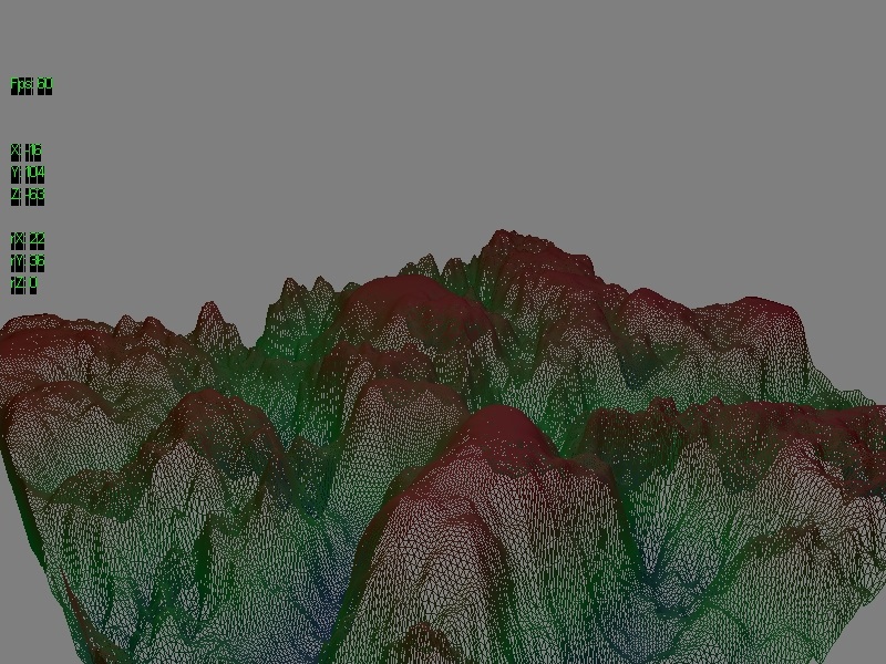
Effectively we're splitting the terrain into two distinct meshes: one triangle mesh representing everything outside the wireframe zone and one line mesh representing everything inside the wireframe zone. If we want to we could even offset these meshes to make the distinction even clearer:
Since we know which specific vertex is outside the wireframe zone we know which edges of the triangle intersect the zone boundary. By finding the intersection points we can have the triangle-outputting shader output a filled sub-triangle up to the zone boundary and the line-outputting shader output wireframe representations of the remaining two sub-triangles, or vice-versa for 1 vertex inside wireframe zone, 2 outside.
Effectively we're splitting the terrain into two distinct meshes: one triangle mesh representing everything outside the wireframe zone and one line mesh representing everything inside the wireframe zone. If we want to we could even offset these meshes to make the distinction even clearer:
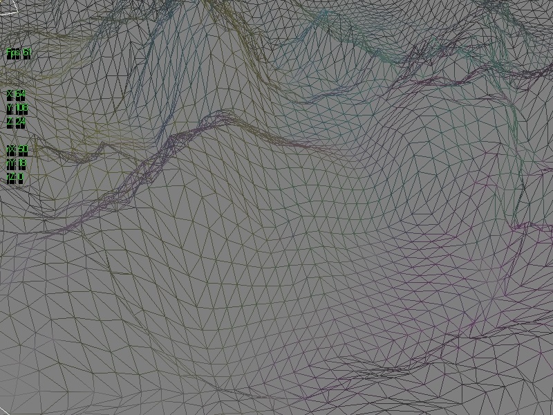
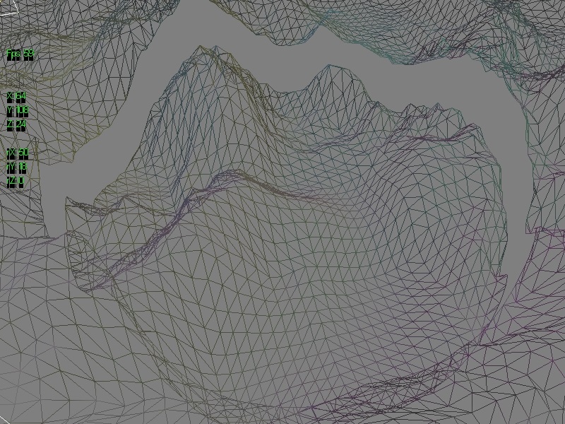
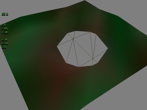
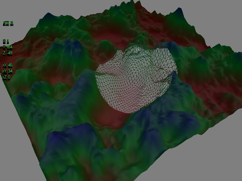
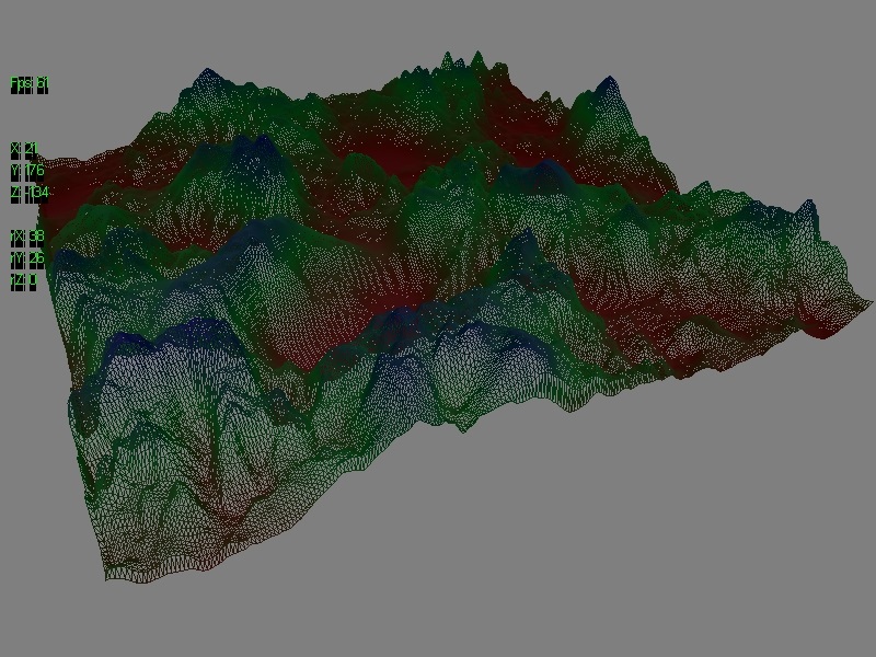
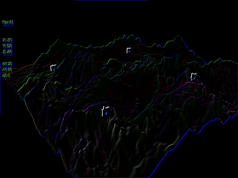
It's clear from what I've shown so far that the wireframe zone is represented as a sphere. Triangles on the boundary of the sphere are cut across linearly, approximating the surface of the sphere. If the terrain has been tessellated to have a decent number of triangles this creates a fairly round, smooth boundary for the zone. As seen to the right it produces a much more rough shape when the total triangle count of the terrain is low.
Hairy Terrain
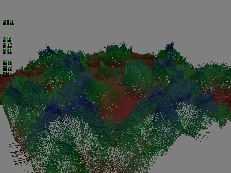
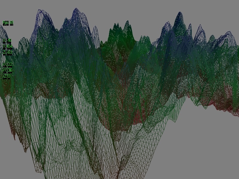
Because we're already running the entire terrain through a geometry shader which outputs a line stream, we can easily add a line for each vertex to represent the direction of the normal to the surface at that point:
Zone Control
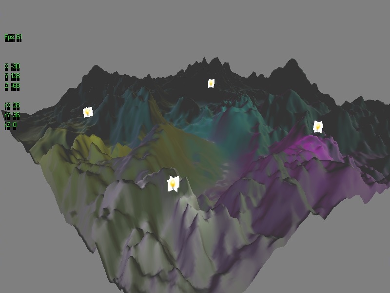
Both the proximity-based tessellation and the proximity-based wireframe are controlled using a ZoneControl struct which has a location in 3D space, a radius, a boolean for snapping the zone centre to the camera's position each frame and a boolean for whether the effect is enabled or not. Both the tessellation and wireframe zones can be moved around independently or snapped to the camera's position, and have the radius expanded or shrunk. Below are some combinations of the various effects I've spoken about in this post and the last. I thoroughly enjoyed this project - there's a lot of really cool things you can do with shaders and I look forward to working some more out.

Download
You can download the program to run for yourself here. You'll need a Windows PC capable of running DirectX11 programs. You'll also need a full keyboard with a numpad: I used a lot of the keyboard for all the toggles and parameter manipulation. Really need to look into hooking up a GUI library...


 RSS Feed
